
A USB Killer doesn’t just fry a port — it uses the victim’s own power against it. Plug one in, and a DC-DC converter inside turns the USB’s 5 V into -10 V to -12 V, storing that charge in capacitors. Once the voltage hits a threshold, a MOSFET switch dumps the stored energy back into the data lines (D+ and D−) and the Vbus pin. The surge can exceed 200 V and 20 A for microseconds, blowing past the port controller and often traveling deeper into the motherboard. The cycle repeats until the port dies or you yank the device. For a defensive cybersecurity learner, building one in a controlled, isolated environment teaches overcurrent protection, USB power negotiation, and real circuit-level weaknesses — no real systems harmed.
How a USB Killer Works
A standard USB Killer consists of a DC-DC converter that steps up the 5 V from the USB port to around -10 V to -12 V, charging a bank of capacitors. Once the capacitors reach a set voltage, a MOSFET switch closes, discharging the stored energy back into the USB data lines (D+ and D−) and the Vbus pin. This surge can exceed 200 V and 20 A for a few microseconds, frying the port controller and often travelling deeper into the system. The loop repeats until the port fails or the device is removed.

Components and Schematic
To build a USB Killer for educational purposes, you need the following components (all widely available and legal to purchase):
- USB A male connector (or USB breakout board)
- DC-DC boost converter module (e.g., MT3608 or similar adjustable step‑up)
- Electrolytic capacitors: 3–4 units of 100 µF, 25 V rating (or higher)
- Small N‑channel MOSFET (e.g., IRF520 or 2N7000)
- Resistors: 10 kΩ, 100 kΩ, and 1 kΩ
- Zener diode (12 V) for voltage clamping
- Prototyping board, wires, soldering iron
The schematic is straightforward: the USB 5 V rail feeds the boost converter, which outputs about 12 V to charge the capacitors via a resistor. A voltage divider (using the 100 kΩ and 10 kΩ resistors) triggers the MOSFET gate when the capacitor voltage reaches ~11 V, discharging the capacitors through the data lines and ground. The Zener diode prevents the gate from exceeding its rating. This design is identical to commercial USB Killers, but built for study purposes only.
Step-by-Step Assembly in a Lab Environment
- Prepare the USB plug. Solder wires to the Vbus (pin 1), D− (pin 2), D+ (pin 3), and GND (pin 4) of the USB connector. Use a breakout board for easier handling.
- Build the boost converter. Connect the input of the MT3608 module to Vbus and GND. Set the output to 12 V using the trim pot and a multimeter.
- Assemble the capacitor bank. Solder the capacitors in parallel on the prototyping board. Connect the positive side to the boost converter’s output through a 10 Ω current‑limiting resistor.
- Add the trigger circuit. Connect the voltage divider across the capacitor bank. The center tap goes to the MOSFET gate. The drain connects to both data lines (D− and D+) via a 1 kΩ resistor; the source goes to GND.
- Final checks. Use a multimeter to verify no shorts between Vbus and GND. Do not plug the device into any live computer.
Before testing, ensure you have a sacrificial test system — an old laptop or a desktop with a dedicated USB PCIe card that you are willing to destroy. Better yet, use a USB power meter and an isolated dummy load (such as a 5 V incandescent bulb) to observe the discharge without damaging any real equipment. Never plug the device into a system you care about.
Safe Testing Protocols
Educational labs should follow strict safety rules:
- Always use a sacrificial USB hub with overt current protection (some hubs will blow a fuse instead of passing the surge to the host).
- Operate in a static‑free area with fire safety equipment nearby.
- Test only on hardware that is physically isolated from networks and contains no sensitive data.
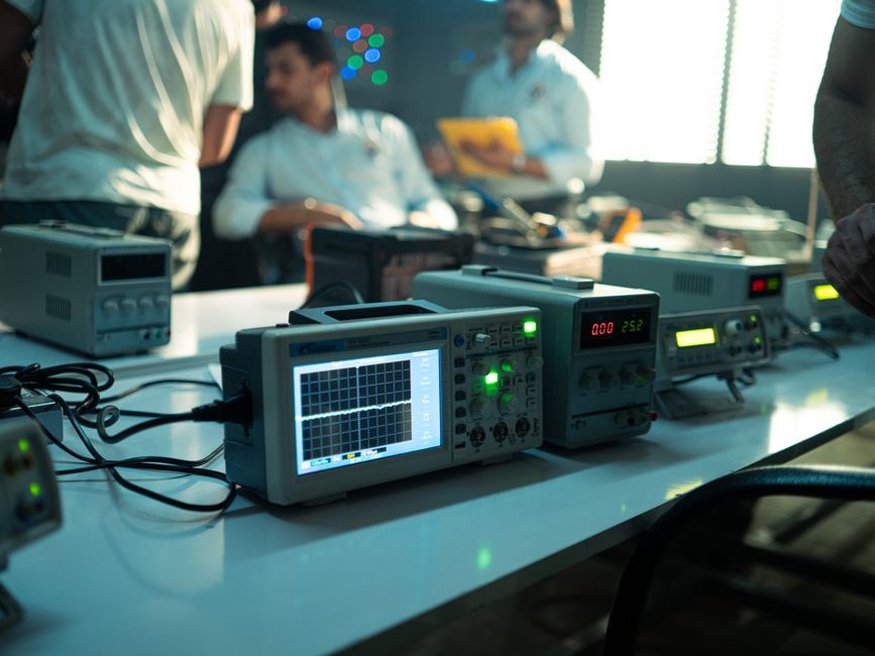
- Record the voltage spike with an oscilloscope (if available) to analyze the waveform — this is the main educational value.
If you are working on Linux, tools like lsusb and usbmon can help monitor USB traffic before and after the test. For a deeper understanding of Linux’s USB subsystem, consider reading practical guides such as our curated list of free books to learn Linux — they cover kernel drivers and power management that directly relate to USB protection mechanisms.
Defensive Measures Against USB Killers
Knowing the attack allows you to defend against it. Here are concrete steps any developer or sysadmin can take:
| Defense Method | How It Works | Implementation |
|---|---|---|
| USB port fuses | Polyfuses or resettable fuses on each port limit current | Add inline PTC fuses (0.5 A) between the motherboard and USB port |
| USB data‑blockers (“USB condoms”) | Pass power but disconnect data lines | Use commercially available sync‑only adapters for charging only |
| Kernel USB guard (Linux) | Kernel module that monitors USB port voltage and disables the port on spikes | Enable CONFIG_USB_OTG and use usbguard with custom rules |
| Physical port locks | Prevent insertion of unauthorized devices | Use USB port blockers on public‑facing terminals |
| BIOS/USB overcurrent protection | Motherboard chipset detects short circuits and shuts off power | Enable “Overcurrent Protection” in BIOS (often on by default on modern boards) |
As a developer, you can also write a simple script that polls /sys/class/power_supply/ on Linux to watch for sudden voltage drops on USB ports (a sign of a short). Combined with logging, this can serve as an early warning. Building such a monitoring tool is a great way to apply programming skills — an ambition we discussed in Dream Big, Code Smart: Why Ambitious Goals Make Better Developers.
Legal and Ethical Boundaries
Constructing and testing a USB Killer is legal in most jurisdictions as long as you own the hardware being tested and it is done for educational purposes. However, using it on any device you do not own — or without explicit permission — constitutes criminal damage. This guide strictly adheres to the ethical principle of defensive cybersecurity: learn the mechanics of an attack to protect systems, not to compromise them. Never carry such a device in public areas where it could be mistaken for a weapon, and always store it in a clearly labeled container.
One practical takeaway: grab one of those cheap $5 USB power meters and hook it up before ever plugging anything suspicious into your main machine. If you see voltage spikes above 5.5 V, you’ll know something’s wrong before hardware fries. Combine that with a Linux script that polls /sys/class/power_supply/usb/ for voltage and current, and you’ve got a DIY early-warning system. Start with the free books to learn Linux to understand the kernel interface, then build up to hardware-level monitoring.